Introduction
The data from Inputs (I) on a Device can be displayed on the platform in graphs (e.g. Analog, CAN Inputs), or states (e.g. Digital Inputs - on/off), while Outputs (O) or Cameras can be toggled from the platform, if supported.
To see the Input data, and to be able to toggle Outputs, you first need to create an IO Type for that IO, and add the corresponding IO on the Device. It is important to know what the IO connection represents, and where the connection is on the Device. For example, if you are looking to immobilise a vehicle from a Digital Output toggle on the platform, and a relay is added to the Device on output 2, name the IO Type Immobiliser and then add that IO Type to output_02.
Before creating IO Types and adding these to the Device, we suggest first confirm the data is being sent to the platform, and the correct values are seen in the telemetry [overview of getting telemetry link here]. Your hardware supplier can advise you what values are expected from the analog/CAN inputs. Digitals will be a 0 or 1 value only.
Related Articles
The data from Inputs can also be reported on, and also trigger alerts. Please follow the links to the article below to see how to use the IO Type data from the Device in the following ways:
1. How do I run reports on the fuel consumption of vehicles?
2. How do I set up fuel theft alerts?
3. How can I tell if a vehicle has filled up?
Create an IO Type
IO types can be created at Vendor or Client levels. The differences and advantages of both levels are listed below:
Vendor Level: all Clients below the Vendor will automatically get the I/O type. This means the I/O type is only created once at Vendor level, rather than multiple times in each Client.
Client Level: if specific I/O Types are used in one or two Clients, adding them at the Client level avoids other Clients seeing the I/Os.
IO Types are all created the same way, and there are one or two differences or values that need to be added to each, as explained below:
ALL IO TYPES
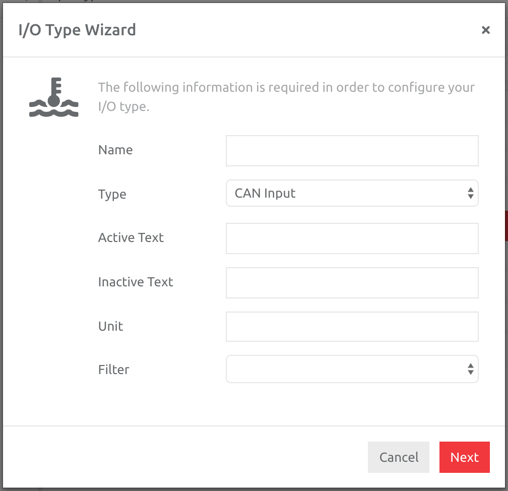
1. Go to Administration,
2. Choose the IO Types section under Profiles,
3. Click the Plus button,
4. Choose the Type and enter the information as required per the IO Type created.
ANALOG INPUTS
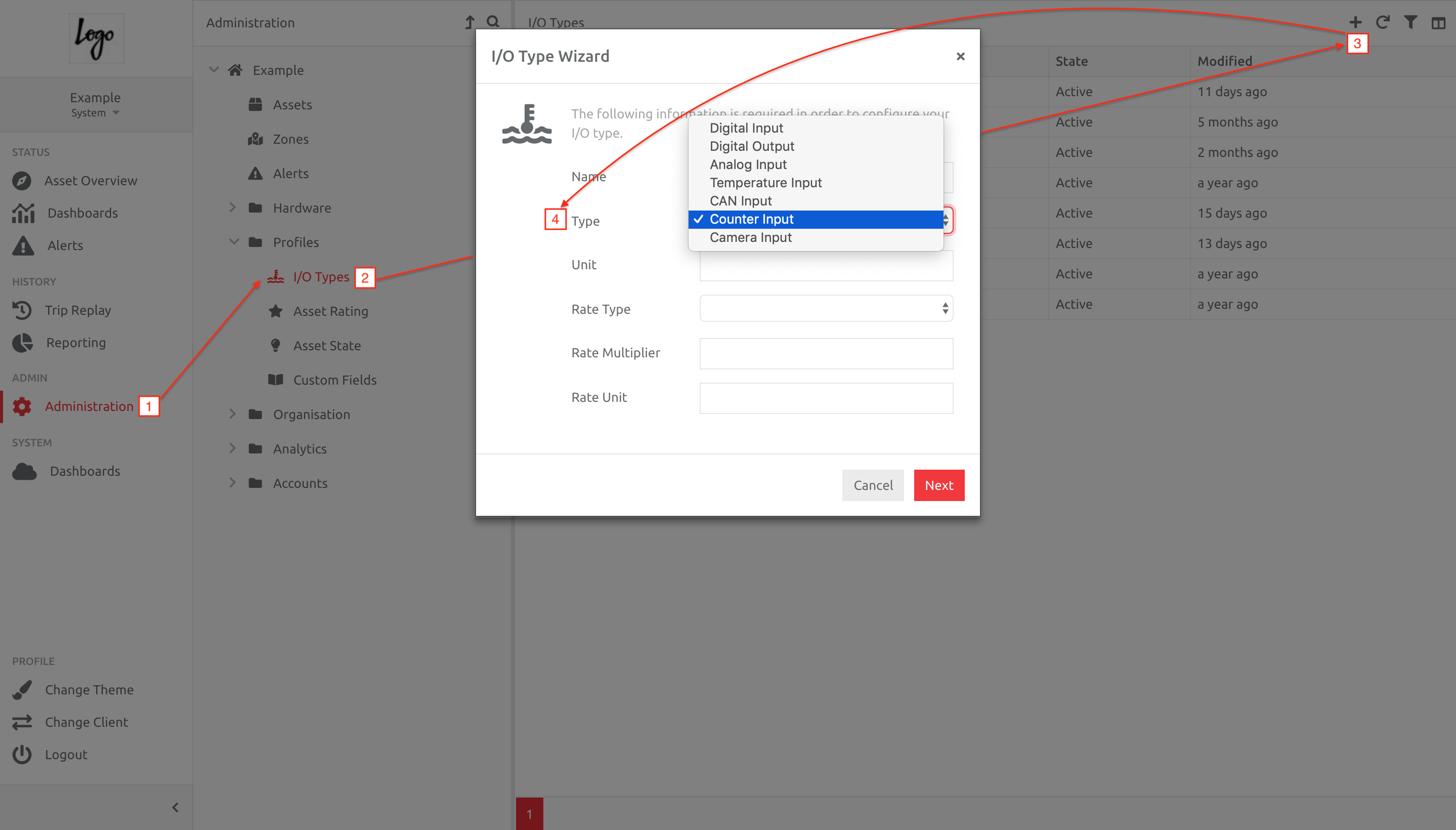
Please enter a Name and Unit (this will show after the value, so a single letter [e.g. L for Litres, V for Voltage] is a good option. You can also choose how many data points you would like to create an Average value from, when showing the data on the front end [None = every data point; 5 samples would use every 5 data points and create an average value from those]: this is useful if the values are not very stable, and you would like to smooth the data line.
CAMERA INPUTS
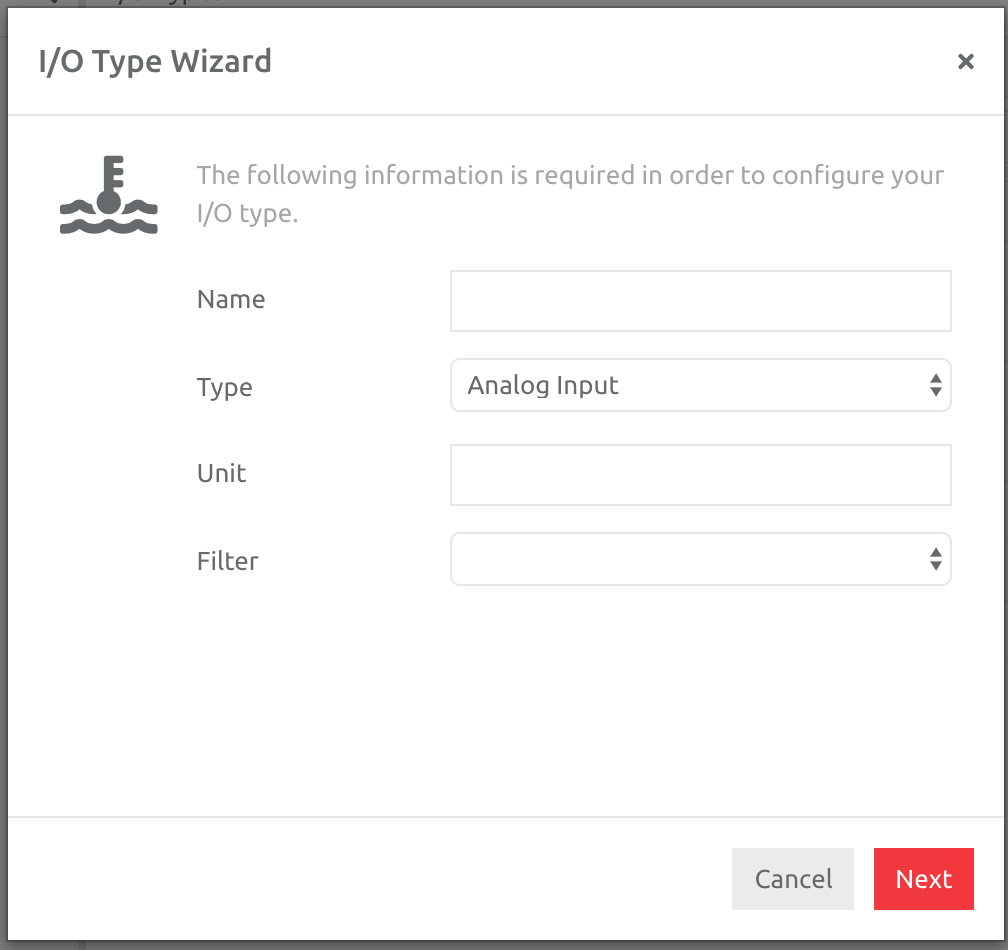
Enter a Name for the Camera Input - a suggestion is to use the position of the camera (e.g. In Cab, External etc) or the number of the camera (e.g. Camera 1, 2 etc).
CAN INPUTS
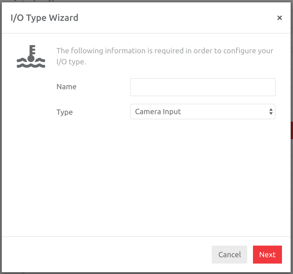
CAN data can be either Digital or Analog data (e.g. PTO, fuel levels etc). Enter a name and the appropriate Text or Units for the IO being created.
COUNTER INPUTS
Counter Inputs reflect data that ticks up, like an Odometer, Engine Hours, Fuel Used (please check with the manufacturer what the value is coming to the platform - Litres or Gallons) etc. This data can be converted into a Rate, such as fuel consumption values, or distance driven per hour.
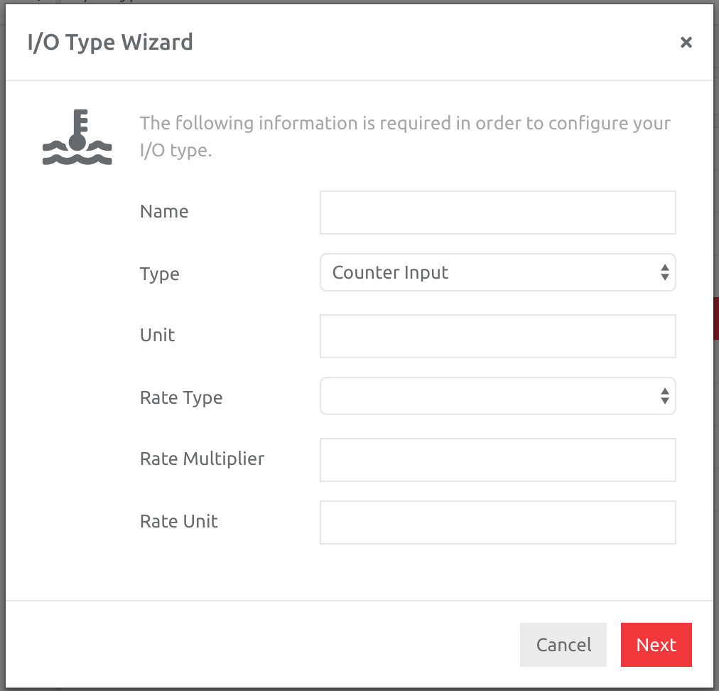
Name the Input and add Units - this will either be Litres (the standard of fuel used from all devices) or Mi/KM (depending on the distance unit chosen in the Client) or H.
The Rate Type and Rate Multiplier depends on whether you would like to measure fuel consumption, or distance per hour. The Rate Type with examples, and multiplier are shown in the table below.
| Rate Type and Examples | Rate Multiplier |
| Value per Kilometer - l/100km | 100 |
| Kilometer per Value - km/l | 1 |
| Value per Mile - gpm | 1 |
| Miles per Value - mpg | 1 |
| Value per Hour - km or mi/h | 1 |
| Hours per Value - h/km or mi | 1 |
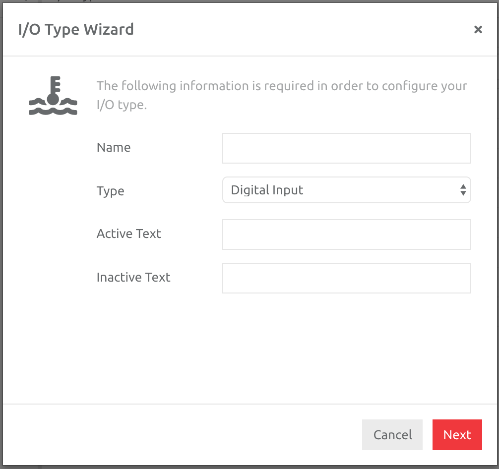
DIGITAL INPUTS & OUTPUTS
Please enter a Name and the Active/Inactive Text you would like to appear on the platform on the Asset.
TEMPERATURE INPUTS
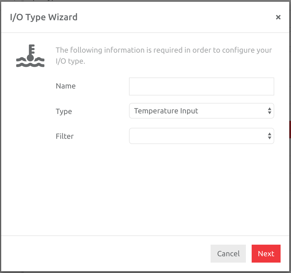
Please enter a Name and choose how many data points you would like to create an Average value from, when showing the data on the front end [None = every data point; 5 samples would use every 5 data points and create an average value from those]: this is useful if you would like to smooth the data line.
VALUE INPUTS
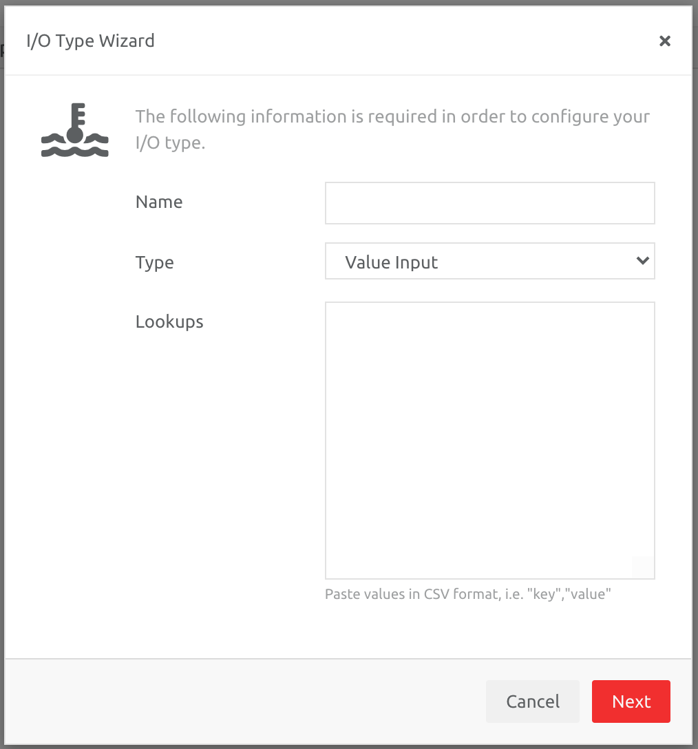
Please enter a Name and add the lookup information in the following format: key,value (example includes DTC code lookups).
Add the IO Type to the Device
Once IO types have been created, these are automatically assigned to Devices and you choose which Input/Output needs to be added to the IO Type.
NB the addition of IO Types can be done in bulk - across many devices. To learn how to do this, follow this link on Editing Information on Multiple Devices]
To add an IO Type/s to one Device:
1. Go to Administration,
2. Choose the Devices section under Hardware,
3. Choose the Device you would like to add the IO Type to, and
4. Choose the I/O section on that Device, and then
5. Choose the Edit option under the correct Input/Output section.
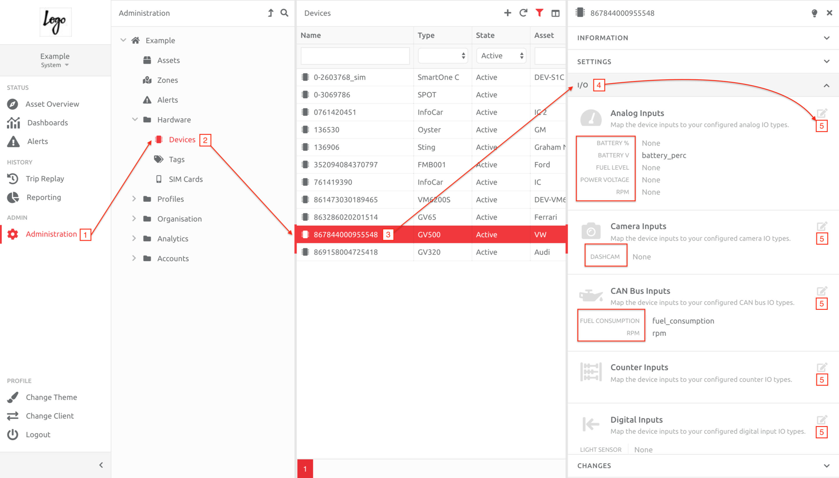
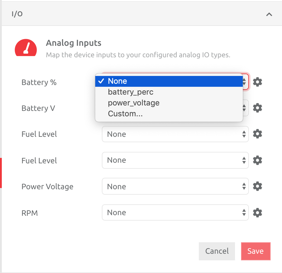
Once the edit option is chosen, you are able to choose the IO Type you would like to add, and then choose the appropriate Input/Output from the drop down list. In this example, the
choices for this Device under the Analog Inputs appear:
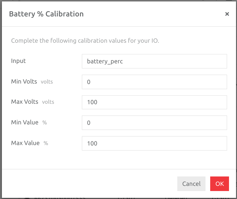
Once you choose the correct Input/Output, another box pop up box appears (except for Camera and Temperature Inputs), to ensure the calibration is correct. See below for each IO Type.
ANALOG INPUTS
Please check with your hardware provider whether the data coming to the platform on the Analog Input is in Voltage, Amperage or the actual value. Please see the attached PDF document explaining how to calibrate sensors if the value is Voltage or Amperage and how to get the Min and Max Volts values.
The Calibration values act as a multiplier on the raw data. If left as is, i.e. 0, 100 and 0, 100, the multiplier is 1. If the device is sending in a value that needs to be multiplied, the min and max values per input need to be set based on the calibration.
In the example below, the data coming in is percentage, and requires no multiplication (i.e. multiplier = 1), hence Min = 0, and Max = 100 for both inputs.
In the screenshots below, the three graphs are from Analog data for RPM, Fuel Consumption and Battery Voltage

CAN INPUTS
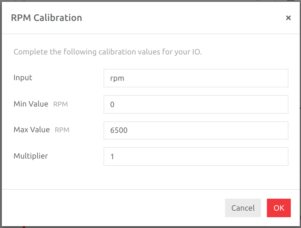
Enter the minimum and maximum values of the item being measured, as per Analog Inputs. If there is a multiplier, please add this to the Input (please consult the Device configuration document to see if there are specific multipliers for the CAN Inputs, or contact your hardware provider to check whether there are specific multipliers to be added).
COUNTER INPUTS
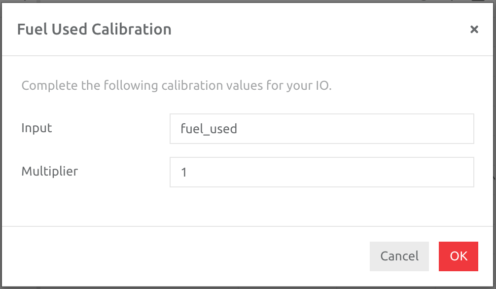
If there is a multiplier for the value coming in from the device, please add this to the Input (please consult the Device configuration document to see if there are specific multipliers for the Counter Inputs, or contact your hardware provider to check whether there are specific multipliers to be added).
DIGITAL INPUTS & OUTPUTS
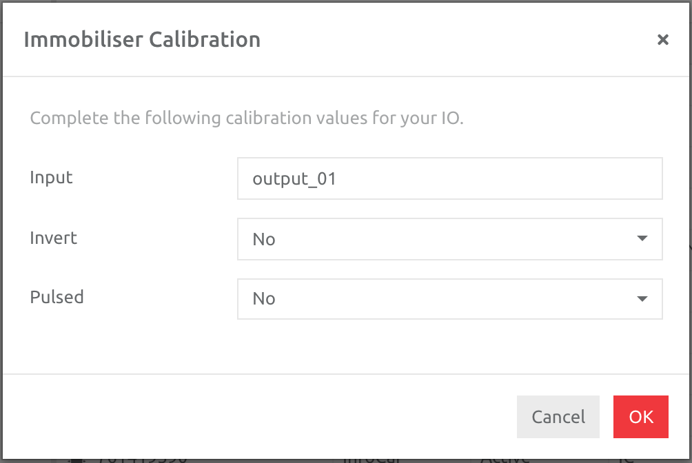
Confirm whether the Digital is inverted, and in the case of Outputs, whether this is pulsed.
TEMPERATURE INPUTS
Please enter a Name and choose how many data points you would like to create an Average value from, when showing the data on the front end [None = every data point; 5 samples would use every 5 data points and create an average value from those]: this is useful if you would like to smooth the data line.
Using I/O Type Data to Create Alerts
Please follow this link to the article outlining how to set up alerts from IO Type data: Asset Events
Comments
0 comments
Please sign in to leave a comment.